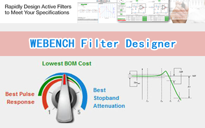
WEBENCH Filter Designer
Loading the player...
将在30s后自动为您播放下一课程
Hi, my name is bobby baker And I work for the WEBENCH filter team I'm here to talk to you about the WEBENCH analog filter designer In all analog systems you'll have a filter that will appear someplace one place or another For instance in data acquisition systems they have the anti-alias filter and the anti-alias filter is actually a low pass filter You would have a band pass filter if you're doing under-sampling activities in your system Or if you want to get rid of 50 or 60Hz or even the switching noise from your power supply you would use a band-stop filter or typically called a notch filter So I'm going to talk to you about the WEBENCH filter Active filter designer from TI we took the filter pro from TI and combine that with the active filter designer from national semiconductor And we took those two and combine the software and took the best of both And came up with an optimum filter solution We used the formulas and the intent verbatim as we went forward So how did we do this We came out with a filter program that would easily be implemented you know for you at your desk on the web You get into this filter program you run You figure out how to select the kind of filter you want And you then design it And then you take a while to analyze it So it's very easy 3 steps Select, design and analyze So enough talk right now Let's get down to the software and take a look at it Up here I have the the cover page for the filter designer The way you get to that is you type in ti.com/WEBENCHfilters And here we are right here And this is what will appear And here you can actually select the low pass or the high pass band pass,etc filter here But also there's a little tutorial It will help you go forward But we're not get a mess around with that We're going to go forward And we're going to just start our design as low pass filter And here we go OK so now we're into the filter program And again this shows up the low pass,high pass, band pass types show up But I'm choosing not to change that I'm sticking with low pass And moving down here I have the attenuation selection and stop and selection in the power supply selection But let's just let this go and I'm going to design a low pass filter for a sensor system And I know that sensors are at low frequency And I know I want to get rid of a lot of noises in the higher frequencies as long as much as I can get rid of so let's enter change Instead of making the cut-off frequency 1000Hz I'm going to make the cutoff frequency 10Hz And that's right here And then I'm moving down and I want the stop-band frequency which by the way happens to be right here making the stop-band frequency 50Hz And let me get rid of two zeros So my filter is going to have a cutoff frequency of 10Hz and down to 50Hz It'll take 45dB to get down to 50Hz So let's see if go with this I also would like a single supply And I would like to design it with a 5V supply So I'm happy with this design And let me go forward and start the filter design Now i'm still in the process of selecting my filter When I go to the next page And in the next page you'll see six panels One is the optimizer the second is changing the inputs I can change the inputs that I just put into the previous screen And I can go back and make some more changes here and with a recalculate Or I can refine these results by changing the order of the filter,etc And you can play with that Down here in the bottom there is an advanced charting panel and solutions panel in the chart The advanced charting panel is actually has all of these solutions that are in in bubble forms so you can change the x axis and the y axis according to the filter order Let's just try that And you'll get something that looks like that Let me change it back to attenuation And I get something like that That's changing the y axis Or you can change the bubbles to zero and on the maximum Q which is very interesting When I pop on a bubble that I like that solution shows up here It pops into view if I pop on this bubble I like It's pops into view again OK so here I have my solutions Notice you have the in this graph you have the color, the order the max Q attenuation etc You can go through that The color is really interesting because when I look at this black and yellow and magenta I go over to these charts and I want to look at the settling time I'm going to zoom in and here And notice that the black line is here That is actually your butterworth solution And so it doesn't settle very well And the magenta line is the linear phase at 0.5°, etc So that's really interesting using the chart to finally zero in on your circuit And another place that I'm going to look in is the optimizer And I'd like to play with this one This is set for three which is the default setting meaning the lowest cost if I change it to two I'll get the lowest settling time And that filter will show up at the top of the solution here And it happens to be a Bessel I'm not surprised the Bessel is a pretty good settling kind of filter And if I want to change it to the the lowest pass band ripple I'll flip it to here And the butterworth is the one that is it behaves the best in the passband I'm going to select that because I like that kind of behavior So now I move past the select phase Now i'm going to move into the design phase with this program And in this program you'll have in the center you'll have the circuit diagrams in the center And then along the left you'll be able to make some more selections And wholly and really fix your design On the top you have the description of each of the filters underneath it And underneath there we have the bill of materials for each of the filter for each of the filter So let's see let's go along this left column And I want to stop here I can change my Op-amp and we're going to come back and do that in just a second I can also change the filter topology specification by changing,let's say, to a multiple feedback instead of the sallen key I like that choice And I say recalculate or update, I guess And it goes through that and you'll notice that a multiple feedback circuit will appear on the screen there it is And here is the VCM which is halfway between the supply and ground to help it work in a single supply environment Moving down this left column again I can tweak the design by changing it from a butterworth to something else at this point Or I can change the order of my filter which means that this would fall off much faster And every time I make those changes I need to update it I am going to select another amplifier And let's see what I'm it will give me I'm looking for the OPA2244 and there is And that has been plugged in And from there I am now going to move into the analysis state So I finished my design I'm happy with the design And I'm going to in the analysis stage In this stage, first of all this system once I pop into this page it immediately will simulate the closed loop frequency response And you'll notice here that the cut-off frequency is 10kHz like we had said it should be And it falls off as a fourth order filter would fall off And here's a phase response sitting right here I can choose to do other simulations I can choose for the sine wave simulation response Or I can choose for a step response In each instance I have the ability to change the input signal In this case it's the high and the low the step response the delay and the rise and the fall time in the pulse width And I can do those kind of variations If I run this step response I'll come up with this kind of response here And here she comes there you go nice step response there It's a better worth it looks good I'm not crazy about that I'd like to just see this, the output And I'm going to delete the input signal here and I did that through the wave form controls up here And now I just have the output signal here So I'm happy with this And I'm going to print a design report The design report comes up in a PDF format And you can say this to your computer Or you can send it to your neighbors etc etc This is what the design report looks like And there is your figure your circuit diagram followed by the bill of materials You'll notice that these capacitors and these capacitors and resistors have manufacturers They are real and you can order them At this point easily And then the design inputs are listed right here that we went through and then one at a time it goes through each state and explains what the Q of that stage was on the topology and which stage number and you know cut-off frequency,etc All of that information is there This concludes our tour through the WEBENCH filter designer As you can see we went through And we did a selection phase And we went and designed your filter And then we went into an analysis stage And finally we ended up with the filter in just a minute If you want to get to use this tool please plug in at ti.com/webenchfilters
Hi, my name is bobby baker And I work for the WEBENCH filter team I'm here to talk to you about the WEBENCH analog filter designer In all analog systems you'll have a filter that will appear someplace one place or another For instance in data acquisition systems they have the anti-alias filter and the anti-alias filter is actually a low pass filter You would have a band pass filter if you're doing under-sampling activities in your system Or if you want to get rid of 50 or 60Hz or even the switching noise from your power supply you would use a band-stop filter or typically called a notch filter So I'm going to talk to you about the WEBENCH filter Active filter designer from TI we took the filter pro from TI and combine that with the active filter designer from national semiconductor And we took those two and combine the software and took the best of both And came up with an optimum filter solution We used the formulas and the intent verbatim as we went forward So how did we do this We came out with a filter program that would easily be implemented you know for you at your desk on the web You get into this filter program you run You figure out how to select the kind of filter you want And you then design it And then you take a while to analyze it So it's very easy 3 steps Select, design and analyze So enough talk right now Let's get down to the software and take a look at it Up here I have the the cover page for the filter designer The way you get to that is you type in ti.com/WEBENCHfilters And here we are right here And this is what will appear And here you can actually select the low pass or the high pass band pass,etc filter here But also there's a little tutorial It will help you go forward But we're not get a mess around with that We're going to go forward And we're going to just start our design as low pass filter And here we go OK so now we're into the filter program And again this shows up the low pass,high pass, band pass types show up But I'm choosing not to change that I'm sticking with low pass And moving down here I have the attenuation selection and stop and selection in the power supply selection But let's just let this go and I'm going to design a low pass filter for a sensor system And I know that sensors are at low frequency And I know I want to get rid of a lot of noises in the higher frequencies as long as much as I can get rid of so let's enter change Instead of making the cut-off frequency 1000Hz I'm going to make the cutoff frequency 10Hz And that's right here And then I'm moving down and I want the stop-band frequency which by the way happens to be right here making the stop-band frequency 50Hz And let me get rid of two zeros So my filter is going to have a cutoff frequency of 10Hz and down to 50Hz It'll take 45dB to get down to 50Hz So let's see if go with this I also would like a single supply And I would like to design it with a 5V supply So I'm happy with this design And let me go forward and start the filter design Now i'm still in the process of selecting my filter When I go to the next page And in the next page you'll see six panels One is the optimizer the second is changing the inputs I can change the inputs that I just put into the previous screen And I can go back and make some more changes here and with a recalculate Or I can refine these results by changing the order of the filter,etc And you can play with that Down here in the bottom there is an advanced charting panel and solutions panel in the chart The advanced charting panel is actually has all of these solutions that are in in bubble forms so you can change the x axis and the y axis according to the filter order Let's just try that And you'll get something that looks like that Let me change it back to attenuation And I get something like that That's changing the y axis Or you can change the bubbles to zero and on the maximum Q which is very interesting When I pop on a bubble that I like that solution shows up here It pops into view if I pop on this bubble I like It's pops into view again OK so here I have my solutions Notice you have the in this graph you have the color, the order the max Q attenuation etc You can go through that The color is really interesting because when I look at this black and yellow and magenta I go over to these charts and I want to look at the settling time I'm going to zoom in and here And notice that the black line is here That is actually your butterworth solution And so it doesn't settle very well And the magenta line is the linear phase at 0.5°, etc So that's really interesting using the chart to finally zero in on your circuit And another place that I'm going to look in is the optimizer And I'd like to play with this one This is set for three which is the default setting meaning the lowest cost if I change it to two I'll get the lowest settling time And that filter will show up at the top of the solution here And it happens to be a Bessel I'm not surprised the Bessel is a pretty good settling kind of filter And if I want to change it to the the lowest pass band ripple I'll flip it to here And the butterworth is the one that is it behaves the best in the passband I'm going to select that because I like that kind of behavior So now I move past the select phase Now i'm going to move into the design phase with this program And in this program you'll have in the center you'll have the circuit diagrams in the center And then along the left you'll be able to make some more selections And wholly and really fix your design On the top you have the description of each of the filters underneath it And underneath there we have the bill of materials for each of the filter for each of the filter So let's see let's go along this left column And I want to stop here I can change my Op-amp and we're going to come back and do that in just a second I can also change the filter topology specification by changing,let's say, to a multiple feedback instead of the sallen key I like that choice And I say recalculate or update, I guess And it goes through that and you'll notice that a multiple feedback circuit will appear on the screen there it is And here is the VCM which is halfway between the supply and ground to help it work in a single supply environment Moving down this left column again I can tweak the design by changing it from a butterworth to something else at this point Or I can change the order of my filter which means that this would fall off much faster And every time I make those changes I need to update it I am going to select another amplifier And let's see what I'm it will give me I'm looking for the OPA2244 and there is And that has been plugged in And from there I am now going to move into the analysis state So I finished my design I'm happy with the design And I'm going to in the analysis stage In this stage, first of all this system once I pop into this page it immediately will simulate the closed loop frequency response And you'll notice here that the cut-off frequency is 10kHz like we had said it should be And it falls off as a fourth order filter would fall off And here's a phase response sitting right here I can choose to do other simulations I can choose for the sine wave simulation response Or I can choose for a step response In each instance I have the ability to change the input signal In this case it's the high and the low the step response the delay and the rise and the fall time in the pulse width And I can do those kind of variations If I run this step response I'll come up with this kind of response here And here she comes there you go nice step response there It's a better worth it looks good I'm not crazy about that I'd like to just see this, the output And I'm going to delete the input signal here and I did that through the wave form controls up here And now I just have the output signal here So I'm happy with this And I'm going to print a design report The design report comes up in a PDF format And you can say this to your computer Or you can send it to your neighbors etc etc This is what the design report looks like And there is your figure your circuit diagram followed by the bill of materials You'll notice that these capacitors and these capacitors and resistors have manufacturers They are real and you can order them At this point easily And then the design inputs are listed right here that we went through and then one at a time it goes through each state and explains what the Q of that stage was on the topology and which stage number and you know cut-off frequency,etc All of that information is there This concludes our tour through the WEBENCH filter designer As you can see we went through And we did a selection phase And we went and designed your filter And then we went into an analysis stage And finally we ended up with the filter in just a minute If you want to get to use this tool please plug in at ti.com/webenchfilters
Hi, my name is bobby baker
And I work for the WEBENCH filter team
I'm here to talk to you
about the WEBENCH analog filter designer
In all analog systems you'll have a filter
that will appear someplace one place or another
For instance in data acquisition systems
they have the anti-alias filter
and the anti-alias filter is
actually a low pass filter
You would have a band pass filter
if you're doing under-sampling activities
in your system
Or if you want to get rid of 50 or 60Hz
or even the switching noise
from your power supply
you would use a band-stop filter
or typically called a notch filter
So I'm going to talk to you
about the WEBENCH filter
Active filter designer from TI
we took the filter pro from TI
and combine that with the active filter designer
from national semiconductor
And we took those two
and combine the software
and took the best of both
And came up with an optimum filter solution
We used the formulas and the intent verbatim
as we went forward
So how did we do this
We came out with a filter program
that would easily be implemented
you know
for you at your desk on the web
You get into this filter program you run
You figure out how to
select the kind of filter you want
And you then design it
And then you take a while to analyze it
So it's very easy 3 steps
Select, design and analyze
So enough talk right now
Let's get down to the software
and take a look at it
Up here I have the the cover page
for the filter designer
The way you get to that is
you type in ti.com/WEBENCHfilters
And here we are right here
And this is what will appear
And here you can actually
select the low pass or the high pass
band pass,etc filter here
But also there's a little tutorial
It will help you go forward
But we're not get a mess around with that
We're going to go forward
And we're going to just start
our design as low pass filter
And here we go
OK so now we're into the filter program
And again this shows up
the low pass,high pass, band pass
types show up
But I'm choosing not to change that
I'm sticking with low pass
And moving down here
I have the attenuation selection and stop
and selection in the power supply selection
But let's just let this go and
I'm going to design a low pass filter
for a sensor system
And I know that sensors are at low frequency
And I know I want to
get rid of a lot of noises
in the higher frequencies
as long as much as I can get rid of
so let's enter change
Instead of making the cut-off frequency 1000Hz
I'm going to make the cutoff frequency 10Hz
And that's right here
And then I'm moving down
and I want the stop-band frequency
which by the way happens to be right here
making the stop-band frequency 50Hz
And let me get rid of two zeros
So my filter is going to have
a cutoff frequency of 10Hz and down to 50Hz
It'll take 45dB to get down to 50Hz
So let's see if go with this
I also would like a single supply
And I would like to design
it with a 5V supply
So I'm happy with this design
And let me go forward
and start the filter design
Now i'm still in the process
of selecting my filter
When I go to the next page
And in the next page you'll see six panels
One is the optimizer
the second is changing the inputs
I can change the inputs
that I just put into the previous screen
And I can go back
and make some more changes here
and with a recalculate
Or I can refine these results
by changing the order of the filter,etc
And you can play with that
Down here in the bottom
there is an advanced charting panel
and solutions panel in the chart
The advanced charting panel
is actually has all of these solutions
that are in in bubble forms
so you can change the x axis and the y axis
according to the filter order
Let's just try that
And you'll get something that looks like that
Let me change it back to attenuation
And I get something like that
That's changing the y axis
Or you can change the bubbles to zero
and on the maximum Q
which is very interesting
When I pop on a bubble that I like
that solution shows up
here It pops into view
if I pop on this bubble I like
It's pops into view again
OK so here I have my solutions
Notice you have the
in this graph you have the color, the order
the max Q attenuation etc
You can go through that
The color is really interesting
because when I look at this black
and yellow and magenta
I go over to these charts
and I want to look at the settling time
I'm going to zoom in and here
And notice that the black line is here
That is actually your butterworth solution
And so it doesn't settle very well
And the magenta line is
the linear phase at 0.5°, etc
So that's really interesting
using the chart to finally
zero in on your circuit
And another place that I'm going to look in
is the optimizer
And I'd like to play with this one
This is set for three
which is the default setting
meaning the lowest cost
if I change it to two
I'll get the lowest settling time
And that filter will show up
at the top of the solution here
And it happens to be a Bessel
I'm not surprised the Bessel
is a pretty good settling kind of filter
And if I want to change it
to the the lowest pass band ripple
I'll flip it to here
And the butterworth is the one
that is it behaves the best in the passband
I'm going to select that
because I like that kind of behavior
So now I move past the select phase
Now i'm going to move into
the design phase with this program
And in this program you'll have
in the center you'll have
the circuit diagrams in the center
And then along the left
you'll be able to make some more selections
And wholly and really fix your design
On the top you have the description
of each of the filters underneath it
And underneath there
we have the bill of materials
for each of the filter
for each of the filter
So let's see let's go along this left column
And I want to stop here
I can change my Op-amp
and we're going to come back
and do that in just a second
I can also change the filter topology specification
by changing,let's say, to a multiple feedback
instead of the sallen key
I like that choice
And I say recalculate
or update, I guess
And it goes through that
and you'll notice that
a multiple feedback circuit
will appear on the screen
there it is
And here is the VCM which is halfway
between the supply and ground
to help it work
in a single supply environment
Moving down this left column again
I can tweak the design
by changing it from a butterworth
to something else at this point
Or I can change the order
of my filter which means that
this would fall off much faster
And every time I make those changes
I need to update it
I am going to select another amplifier
And let's see what I'm
it will give me
I'm looking for the OPA2244
and there is
And that has been plugged in
And from there I am now
going to move into the analysis state
So I finished my design
I'm happy with the design
And I'm going to in the analysis stage
In this stage, first of all
this system once I pop into this page
it immediately will simulate
the closed loop frequency response
And you'll notice here that
the cut-off frequency is 10kHz
like we had said it should be
And it falls off
as a fourth order filter would fall off
And here's a phase response
sitting right here
I can choose to do other simulations
I can choose for the
sine wave simulation response
Or I can choose for a step response
In each instance I have the ability
to change the input signal
In this case it's the high and the low
the step response
the delay and the rise and the fall time
in the pulse width
And I can do those kind of variations
If I run this step response
I'll come up with this kind of response here
And here she comes
there you go
nice step response there
It's a better worth it looks good
I'm not crazy about that
I'd like to just see this, the output
And I'm going to delete the input signal here
and I did that through
the wave form controls up here
And now I just have the output signal here
So I'm happy with this
And I'm going to print a design report
The design report comes up in a PDF format
And you can say this to your computer
Or you can send it to your neighbors etc etc
This is what the design report looks like
And there is your figure
your circuit diagram
followed by the bill of materials
You'll notice that these capacitors
and these capacitors and resistors
have manufacturers
They are real
and you can order them
At this point easily
And then the design inputs are listed right here
that we went through
and then one at a time
it goes through each state
and explains what the Q of that stage was
on the topology
and which stage number and you know
cut-off frequency,etc
All of that information is there
This concludes our tour
through the WEBENCH filter designer
As you can see we went through
And we did a selection phase
And we went and designed your filter
And then we went into an analysis stage
And finally we ended up with the filter
in just a minute
If you want to get to use this tool
please plug in at ti.com/webenchfilters
手机看
扫码用手机观看
-
 未学习 WEBENCH Filter Designer
00:10:35
播放中
 视频简介
视频简介
WEBENCH Filter Designer
所属课程:WEBENCH Filter Designer
发布时间:2015.05.18
视频集数:1
本节视频时长:00:10:35
介绍WEBENCH 模拟滤波器设计。